Building a Hardened IoT Security Gateway: Raspberry Pi 5, Dual-Interface VLAN Micro-Segmentation, Suricata IDS, and Zigbee Bridge
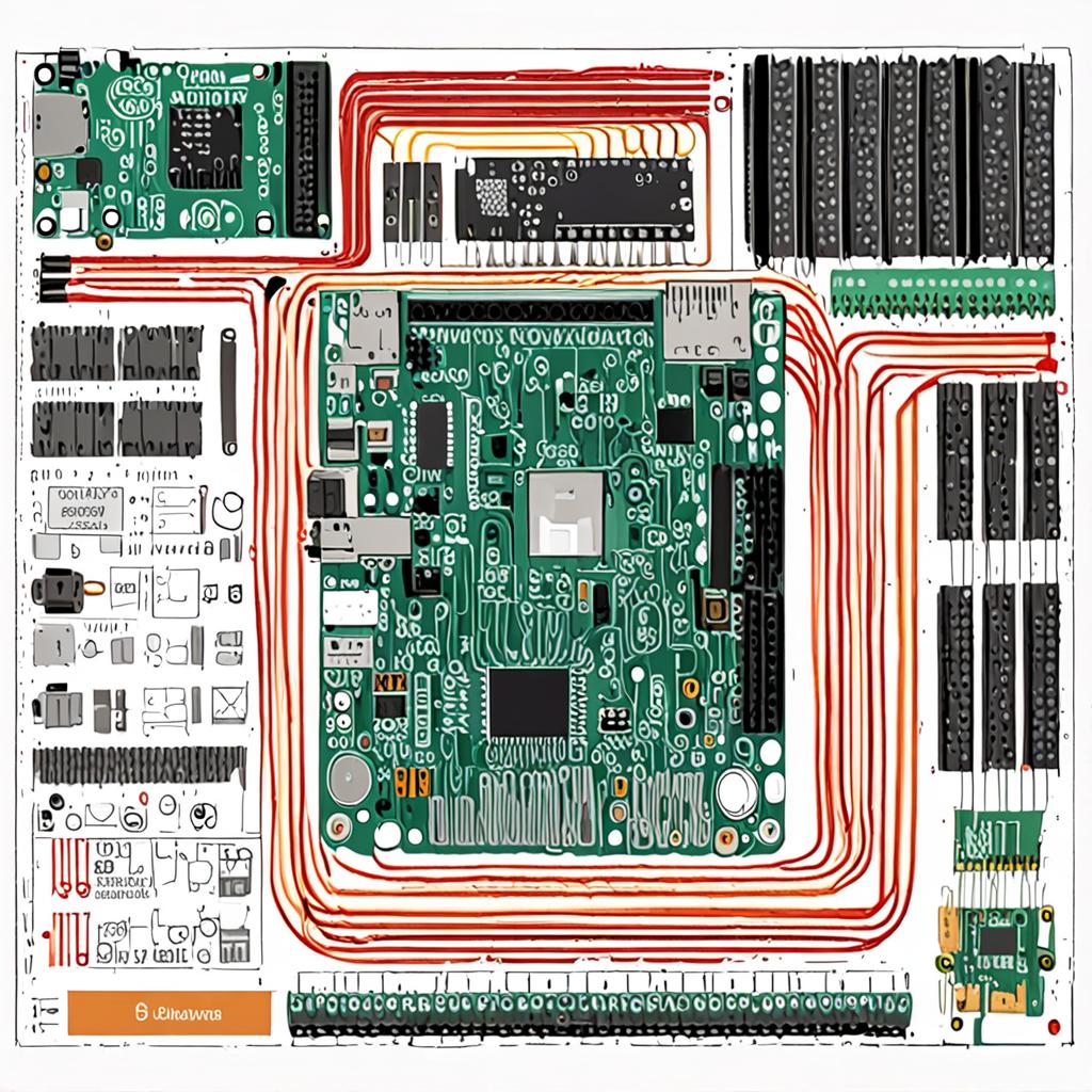
Introduction: The Peril of Flat IoT Networks
The contemporary smart home and industrial edge are saturated with inexpensive microcontroller units, proprietary IP cameras, smart plugs, and environmental sensors. While these devices add convenience and telemetry, they introduce severe operational security vulnerabilities. Most commercial off-the-shelf (COTS) Internet of Things (IoT) hardware ships with hardcoded credentials, unpatched embedded Linux kernels, insecure update mechanisms, and persistent telemetry beacons calling back to opaque cloud infrastructure. When these devices share a flat Layer 2 network with personal workstations, network-attached storage (NAS), and homelab hypervisors, a single compromised sensor allows an adversary to pivot horizontally across the entire subnet.
To eliminate this systemic risk, this guide details how to build a dedicated, hardware-hardened Edge IoT Security Gateway using a Raspberry Pi 5. By leveraging the Raspberry Pi 5’s PCIe 2.0/3.0 interface for dual-gigabit network segmentation, combining kernel-level stateful filtering via nftables, integrating Suricata for real-time Intrusion Detection and Prevention (IDS/IPS), and establishing an isolated hardware bridge for Zigbee 3.0 and I2C telemetry, you can construct an enterprise-grade perimeter for untrusted devices.
Hardware Bill of Materials & Technical Specifications
Building a robust edge gateway requires deliberate hardware selection to ensure sustained I/O throughput, low thermal throttling under deep packet inspection, and reliable bus communication.
| Component | Specification / Model | Role in Architecture |
|---|---|---|
| Single-Board Computer | Raspberry Pi 5 (8GB RAM, Broadcom BCM2712 Quad-core Cortex-A76 @ 2.4GHz) | Central compute, IDS packet inspection, container engine, and packet routing. |
| PCIe Network Expansion | Waveshare PCIe to Gigabit NIC HAT+ (Realtek RTL8168/8111 chipset) | Provides dedicated secondary physical Ethernet interface (eth1) for physical IoT isolation. |
| Zigbee Coordinator | Sonoff Zigbee 3.0 USB Dongle Plus-P (TI CC2652P + CP2102N) with +20dBm amplifier | Dedicated IEEE 802.15.4 local radio coordinator for local IoT sensor mesh. |
| Telemetry Sensor | Bosch BME280 Breakout (I2C interface, addresses 0x76 / 0x77) | Cabinet ambient temperature, relative humidity, and barometric pressure monitoring. |
| Status Display | SSD1306 0.96-inch Monochrome I2C OLED (128x64 pixels, address 0x3C) | Real-time edge telemetry, active IP leases, packet drop counters, and IDS alerts. |
| Power Delivery | Official Raspberry Pi 27W USB-C Power Supply (5.1V / 5.0A with PD negotiation) | Prevents brownouts during simultaneous PCIe I/O bursts and high CPU loads. |
| Storage | M.2 NVMe SSD (256GB PCIe Gen3 x1 via NVMe Base HAT) or Class A2 MicroSD | High-endurance log buffering for Suricata eve.json and SQLite databases. |
Hardware Wiring & Physical Interconnects
The Raspberry Pi 5 provides a 40-pin GPIO header that supports multi-drop I2C communication alongside its external PCIe 16-pin FPC connector. The Bosch BME280 sensor and SSD1306 OLED display share the primary I2C bus (/dev/i2c-1), distinguished by their unique hex addresses (0x76 for BME280 and 0x3C for SSD1306).
Pinout and Bus Interfacing
- Pin 1 (3.3V Power): Connects to VCC on both the BME280 and SSD1306 modules.
- Pin 3 (GPIO 2 / I2C1_SDA): Parallel connection to the SDA lines of both BME280 and SSD1306.
- Pin 5 (GPIO 3 / I2C1_SCL): Parallel connection to the SCL lines of both BME280 and SSD1306.
- Pin 9 (Ground): Common reference ground tied to GND on both sensor and display modules.
- PCIe FPC Header: Connected via 16-pin flat flex cable directly to the Gigabit NIC HAT+.
- USB 3.0 Port (Top): Connected via a 1-meter shielded USB extension cable to the CC2652P Zigbee dongle (minimizing 2.4GHz RF interference from Pi 5 USB 3.0 controllers).
- Interface
eth0(Onboard): Connected to Core Router/Switch (VLAN Trunk carrying Management VLAN 10, Trusted LAN VLAN 20, and IoT VLAN 30). - Interface
eth1(PCIe NIC): Connected to an unmanaged switch dedicated to wired untrusted IoT hardware (192.168.30.0/24 subnet).
OS Preparation & Kernel Hardening
Flash Raspberry Pi OS Lite (64-bit) based on Debian 12 (Bookworm). Boot into the system and edit /boot/firmware/config.txt to initialize hardware buses and enable maximum PCIe Gen 3 throughput.
# Append to /boot/firmware/config.txt
dtparam=i2c_arm=on
dtparam=i2c_arm_baudrate=400000

# Enable PCIe Gen 3 speeds for the secondary NIC
dtparam=pciex1
dtparam=pciex1_gen=3

# Hardware Watchdog timer
dtparam=watchdog=on
Reboot the system, then enforce aggressive Linux kernel network stack hardening against IP spoofing, routing redirects, and SYN flood attacks by creating /etc/sysctl.d/99-iot-gateway.conf:
# Enable IPv4 packet forwarding
net.ipv4.ip_forward = 1
net.ipv4.conf.all.forwarding = 1

# Disable ICMP Redirect acceptance and transmission
net.ipv4.conf.all.send_redirects = 0
net.ipv4.conf.default.send_redirects = 0
net.ipv4.conf.all.accept_redirects = 0
net.ipv4.conf.default.accept_redirects = 0

# Disable source packet routing
net.ipv4.conf.all.accept_source_route = 0
net.ipv4.conf.default.accept_source_route = 0

# Enable strict Reverse Path Filtering (prevents IP spoofing)
net.ipv4.conf.all.rp_filter = 1
net.ipv4.conf.default.rp_filter = 1

# Enable TCP SYN Cookies
net.ipv4.tcp_syncookies = 1

# Log Martians (unroutable/bogus packet addresses)
net.ipv4.conf.all.log_martians = 1
net.ipv4.conf.default.log_martians = 1
Apply the kernel parameters immediately:
sudo sysctl --systemNetwork Topology & Interface Configuration
We utilize systemd-networkd to manage trunking, tagged virtual LANs, and static addressing for the dual-NIC architecture. Disable default networking managers if active and enable systemd-networkd.
sudo systemctl enable --now systemd-networkd systemd-resolved1. Upstream Trunk Interface Configuration
Define the physical trunk on eth0 in /etc/systemd/network/10-eth0.network:
[Match]
Name=eth0

[Network]
VLAN=vlan10
VLAN=vlan20
VLAN=vlan30
LinkLocalAddressing=no
LLDP=no
EmitLLDP=no
2. VLAN Virtual NetDev Declarations
Create the netdev definitions in /etc/systemd/network/20-vlan30.netdev:
[NetDev]
Name=vlan30
Kind=vlan

[VLAN]
Id=30
3. IoT Network Interface Configuration
Bind IP routing and DHCP listening parameters for the IoT network in /etc/systemd/network/30-vlan30.network and the physical secondary port in /etc/systemd/network/40-eth1.network:
# /etc/systemd/network/30-vlan30.network
[Match]
Name=vlan30

[Network]
Address=192.168.30.1/24
ConfigureWithoutCarrier=yes

# /etc/systemd/network/40-eth1.network (Bridge or direct subnet for local physical IoT)
[Match]
Name=eth1

[Network]
Address=192.168.31.1/24
ConfigureWithoutCarrier=yes
Restart networking to instantiate the interfaces:
sudo systemctl restart systemd-networkdStateful Micro-Segmentation with nftables
Replace legacy iptables with native, high-performance nftables. The policy enforces strict zero-trust boundary isolation: Trusted LAN (VLAN 20) can establish stateful sessions into IoT (VLAN 30), but IoT devices are prohibited from initiating sessions into the LAN or Gateway management interfaces.
Create /etc/nftables.conf with the following production ruleset:
#!/usr/sbin/nft -f

flush ruleset

table inet filter {
    # Define address sets
    set trusted_lan {
        type ipv4_addr
        flags interval
        elements = { 10.0.20.0/24 }
    }

    set iot_network {
        type ipv4_addr
        flags interval
        elements = { 192.168.30.0/24, 192.168.31.0/24 }
    }

    set ntp_servers {
        type ipv4_addr
        elements = { 162.159.200.1, 162.159.200.123 }
    }

    chain input {
        type filter hook input priority filter; policy drop;

        # Allow loopback
        iifname "lo" accept

        # Allow established and related traffic
        ct state established,related accept

        # Drop invalid state connections
        ct state invalid drop

        # Allow ICMP ping with rate-limiting
        ip protocol icmp icmp type echo-request limit rate 5/second accept

        # Allow SSH and Management only from Trusted LAN
        ip saddr @trusted_lan tcp dport { 22, 9090 } accept

        # Allow DNS (Port 53) and DHCP (Port 67) from IoT
        ip saddr @iot_network udp dport { 53, 67 } accept
        ip saddr @iot_network tcp dport 53 accept

        # Allow MQTT TLS from IoT devices to local broker
        ip saddr @iot_network tcp dport 8883 accept

        # Log and drop everything else
        limit rate 3/minute burst 5 packets log prefix "[NFT_INPUT_DROP]: "
        drop
    }

    chain forward {
        type filter hook forward priority filter; policy drop;

        # Allow established and related streams
        ct state established,related accept
        ct state invalid drop

        # Allow Trusted LAN to initiate connections to IoT devices
        ip saddr @trusted_lan ip daddr @iot_network accept

        # Allow IoT devices to access specific external NTP servers only
        ip saddr @iot_network ip daddr @ntp_servers udp dport 123 accept

        # Explicitly BLOCK IoT traffic from accessing Trusted LAN or Management
        ip saddr @iot_network ip daddr @trusted_lan drop

        # Log unexpected egress attempts from IoT
        ip saddr @iot_network limit rate 5/minute log prefix "[NFT_IOT_BLOCKED_EGRESS]: "
        drop
    }

    chain postrouting {
        type nat hook postrouting priority srcnat; policy accept;

        # Masquerade outbound NTP or permitted WAN traffic exiting eth0
        oifname "eth0" ip saddr @iot_network masquerade
    }
}
Enable and verify the firewall ruleset:
sudo systemctl enable --now nftables
sudo nft list ruleset
Deploying Suricata IDS for Real-Time Threat Inspection
Suricata operates directly on incoming and routed packets using high-speed AF_PACKET ring buffers, continuously matching traffic signatures against emerging threat databases (ET Open rules).
Installation and Configuration
sudo apt install suricata jq -y
sudo suricata-update
Modify /etc/suricata/suricata.yaml to tune the engine for the Raspberry Pi 5's Cortex-A76 cores and bind to our IoT interfaces:
# Edit /etc/suricata/suricata.yaml
vars:
  address-groups:
    HOME_NET: "[192.168.30.0/24, 192.168.31.0/24]"
    EXTERNAL_NET: "!$HOME_NET"

af-packet:
  - interface: vlan30
    threads: 2
    cluster-id: 99
    cluster-type: cluster_flow
    defrag: yes
    use-mmap: yes
    mmap-locked: yes
    tpacket-v3: yes
    ring-size: 2048
  - interface: eth1
    threads: 2
    cluster-id: 98
    cluster-type: cluster_flow
    defrag: yes
    use-mmap: yes

default-rule-path: /var/lib/suricata/rules
rule-files:
  - suricata.rules

outputs:
  - eve-log:
      enabled: yes
      filetype: regular
      filename: /var/log/suricata/eve.json
      types:
        - alert:
            payload: yes
            payload-printable: yes
            packet: yes
        - anomaly:
            enabled: yes
        - drop:
            alerts: yes
Start and monitor Suricata:
sudo systemctl restart suricata
sudo tail -f /var/log/suricata/eve.json | jq 'select(.event_type=="alert")'
Containerized Services: Mosquitto with TLS & Zigbee2MQTT
To eliminate cloud dependency, IoT devices communicate locally via an encrypted MQTT message broker and Zigbee coordinator running inside isolated Docker containers.
Docker Compose Architecture
Create a dedicated workspace directory at /opt/iot-gateway:
sudo mkdir -p /opt/iot-gateway/mosquitto/config /opt/iot-gateway/mosquitto/certs /opt/iot-gateway/zigbee2mqtt/data
cd /opt/iot-gateway
Create the hardened Mosquitto configuration file at /opt/iot-gateway/mosquitto/config/mosquitto.conf requiring TLS 1.3 encryption:
per_listener_settings true

# Plaintext listener binding strictly to local loopback
listener 1883 127.0.0.1
allow_anonymous false
password_file /mosquitto/config/pwfile

# Secure TLS listener for IoT clients
listener 8883 0.0.0.0
cafile /mosquitto/certs/ca.crt
certfile /mosquitto/certs/server.crt
keyfile /mosquitto/certs/server.key
require_certificate false
tls_version tlsv1.3
allow_anonymous false
password_file /mosquitto/config/pwfile
Create /opt/iot-gateway/docker-compose.yml:
version: "3.8"

services:
  mosquitto:
    image: eclipse-mosquitto:2.0-alpine
    container_name: iot-mosquitto
    restart: unless-stopped
    ports:
      - "127.0.0.1:1883:1883"
      - "192.168.30.1:8883:8883"
      - "192.168.31.1:8883:8883"
    volumes:
      - ./mosquitto/config:/mosquitto/config
      - ./mosquitto/certs:/mosquitto/certs
      - ./mosquitto/data:/mosquitto/data
      - ./mosquitto/log:/mosquitto/log
    security_opt:
      - no-new-privileges:true
    cap_drop:
      - ALL

  zigbee2mqtt:
    image: koenkk/zigbee2mqtt:latest
    container_name: iot-zigbee2mqtt
    restart: unless-stopped
    depends_on:
      - mosquitto
    volumes:
      - ./zigbee2mqtt/data:/app/data
      - /run/udev:/run/udev:ro
    devices:
      - /dev/serial/by-id/usb-ITead_Sonoff_Zigbee_3.0_USB_Dongle_Plus_P_0001-if00-port0:/dev/ttyUSB0
    environment:
      - TZ=UTC
    security_opt:
      - no-new-privileges:true
Configure Zigbee2MQTT in /opt/iot-gateway/zigbee2mqtt/data/configuration.yaml:
homeassistant: false
permit_join: false
mqtt:
  base_topic: zigbee2mqtt
  server: 'mqtt://mosquitto:1883'
  user: 'z2m_admin'
  password: 'StrongGeneratedPasswordHere'
serial:
  port: /dev/ttyUSB0
  adapter: zstack
frontend:
  port: 8080
  host: 127.0.0.1
advanced:
  network_key: GENERATE
  pan_id: GENERATE
  ext_pan_id: GENERATE
  channel: 25
Start the container ecosystem:
docker compose up -dTelemetry & Hardware Display Daemon
To monitor edge health and detect operational anomalies without logging into SSH, a Python daemon reads the BME280 sensor and Suricata alert metrics, rendering the data on the SSD1306 OLED display over I2C.
sudo apt install python3-pip python3-smbus python3-pil -y
pip3 install adafruit-circuitpython-bme280 adafruit-circuitpython-ssd1306 --break-system-packages
Save the script as /opt/iot-gateway/telemetry_display.py:
#!/usr/bin/env python3
import time
import subprocess
import board
import busio
from PIL import Image, ImageDraw, ImageFont
import adafruit_bme280
import adafruit_ssd1306

# Initialize I2C Bus
i2c = busio.I2C(board.SCL, board.SDA)

# Initialize Sensors and Display
oled = adafruit_ssd1306.SSD1306_I2C(128, 64, i2c, addr=0x3C)
bme = adafruit_bme280.Adafruit_BME280_I2C(i2c, address=0x76)

oled.fill(0)
oled.show()

image = Image.new("1", (oled.width, oled.height))
draw = ImageDraw.Draw(image)
font = ImageFont.load_default()

def get_suricata_alert_count():
    try:
        cmd = "grep -c '\"event_type\":\"alert\"' /var/log/suricata/eve.json"
        res = subprocess.check_output(cmd, shell=True).decode().strip()
        return res
    except Exception:
        return "0"

while True:
    draw.rectangle((0, 0, oled.width, oled.height), outline=0, fill=0)

    # Read Telemetry
    temp_c = bme.temperature
    humidity = bme.humidity
    pressure = bme.pressure
    alerts = get_suricata_alert_count()

    # Render Output
    draw.text((0, 0),  "HARDENED IOT GATEWAY", font=font, fill=255)
    draw.text((0, 14), f"Temp: {temp_c:.1f}C  Hum: {humidity:.1f}%", font=font, fill=255)
    draw.text((0, 26), f"Baro: {pressure:.0f} hPa", font=font, fill=255)
    draw.text((0, 38), f"IDS Alerts: {alerts}", font=font, fill=255)
    draw.text((0, 50), "State: ENFORCING", font=font, fill=255)

    oled.image(image)
    oled.show()
    time.sleep(3)
Create a systemd unit file at /etc/systemd/system/gateway-telemetry.service:
[Unit]
Description=Gateway OLED & Sensor Telemetry Daemon
After=network.target

[Service]
Type=simple
User=root
ExecStart=/usr/bin/python3 /opt/iot-gateway/telemetry_display.py
Restart=always
RestartSec=5

[Install]
WantedBy=multi-user.target
sudo systemctl enable --now gateway-telemetry.serviceVerification, Testing & Troubleshooting Guide
1. Verification Commands
- I2C Bus Inspection: Verify both devices are registered on I2C bus 1:
Expected output: addressessudo i2cdetect -y 10x3cand0x76must be populated. - IDS Engine Status: Check live packet counters:
sudo suricatasc -c "iface-stat vlan30" - Firewall Ingress Rejection Test: From an untrusted IoT IP (e.g., 192.168.30.50), attempt to SSH into the Trusted LAN:
The connection must immediately timeout or reset, triggering an entry inssh admin@10.0.20.5sudo dmesg | grep NFT_IOT_BLOCKED.
2. Diagnostic Matrix
| Symptom | Probable Root Cause | Remediation Protocol |
|---|---|---|
i2cdetect shows no devices or hangs |
Loose SDA/SCL jumpers or pull-up voltage mismatch. | Check 3.3V supply pin; verify pull-up resistors (Raspberry Pi 5 has built-in 1.8k pull-ups on GPIO 2/3). |
| Suricata drops high percentage of packets | AF_PACKET ring buffer starvation under load. | Increase ring-size to 4096 in suricata.yaml and pin threads to isolated CPU cores using isolcpus. |
| Zigbee coordinator drops connection intermittently | USB 3.0 controller EMI radiating into 2.4GHz antenna. | Move coordinator to an external powered USB 2.0 hub or use a 1m shielded USB extension cable away from the board. |
| IoT devices unable to obtain IP lease | DHCP request blocked by nftables. |
Verify UDP port 67/68 is accepted in the nftables input chain for interface vlan30 and eth1. |
Security Considerations & Maintenance
- Read-Only Partitioning & Log Rotation: Deep packet inspection writes large volumes of telemetry. Configure log rotation for
/var/log/suricata/eve.jsonwith a 48-hour retention limit or stream logs to an external hardened Syslog server over TLS to prevent SSD wear. - Microcontroller Firmware Auditing: Periodically flash updated Zigbee coordinator firmware (e.g., Koenkk Z-Stack) using
cc2538-bslto patch zero-day vulnerabilities in the 802.15.4 MAC layer. - Unattended Upgrades: Enable Debian
unattended-upgradesstrictly for critical security patches:sudo apt install unattended-upgrades && sudo dpkg-reconfigure --priority=low unattended-upgrades
Conclusion
By transforming the Raspberry Pi 5 into a hardened edge gateway, you dismantle the single flat network architecture that makes IoT vulnerabilities dangerous. With dual physical/virtual segmentation via systemd-networkd, non-bypassable stateful filtering via nftables, real-time threat detection with Suricata, and completely local Zigbee/MQTT orchestration, your homelab and internal subnets remain completely isolated from compromised smart hardware.


Comments
Post a Comment